

Arduino Potentiometer Sensor Kit Price in Pakistan | AmpFlick
Original price was: ₨2,000.00.₨1,900.00Current price is: ₨1,900.00.
Delivered All over Pakistan 🇵🇰
The Arduino Potentiometer Sensor Kit features an ATmega328P based microcontroller and a 10K linear potentiometer. It includes a 400-point breadboard for rapid prototyping of analog input circuits. A 220-ohm resistor and a 5mm LED are provided for visual feedback of signal processing. Specifically, the system utilizes the 10-bit ADC of the Arduino to read variable voltage levels
Description
Master Analog Input with the Arduino Potentiometer Sensor Kit
This technical training set enables users to translate mechanical rotation into digital data for precise device control. Therefore, using the Arduino Potentiometer Sensor Kit is a perfect way to learn about Analog-to-Digital Conversion (ADC). The core system utilizes an Arduino UNO to process voltage changes from a high-quality rotary dial. Additionally, the kit includes an LED and a 220-ohm resistor to visualize the variable output levels. However, the breadboard interface allows you to modify the circuit for various sensing experiments quite easily.
Technical Specifications for Arduino Potentiometer Sensor Kit
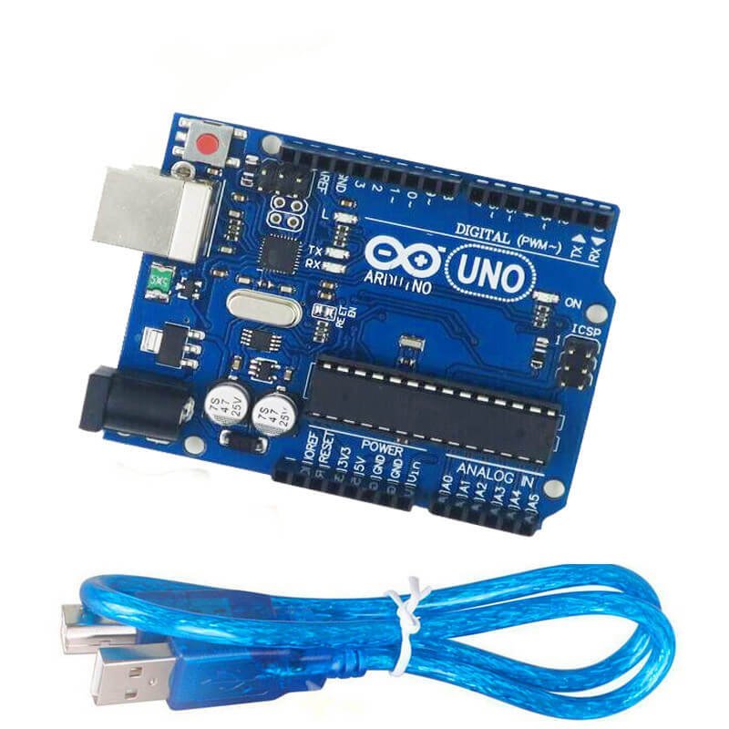
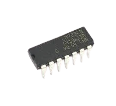
Microcontroller: Arduino UNO R3 compatible board with ATmega328P processor.
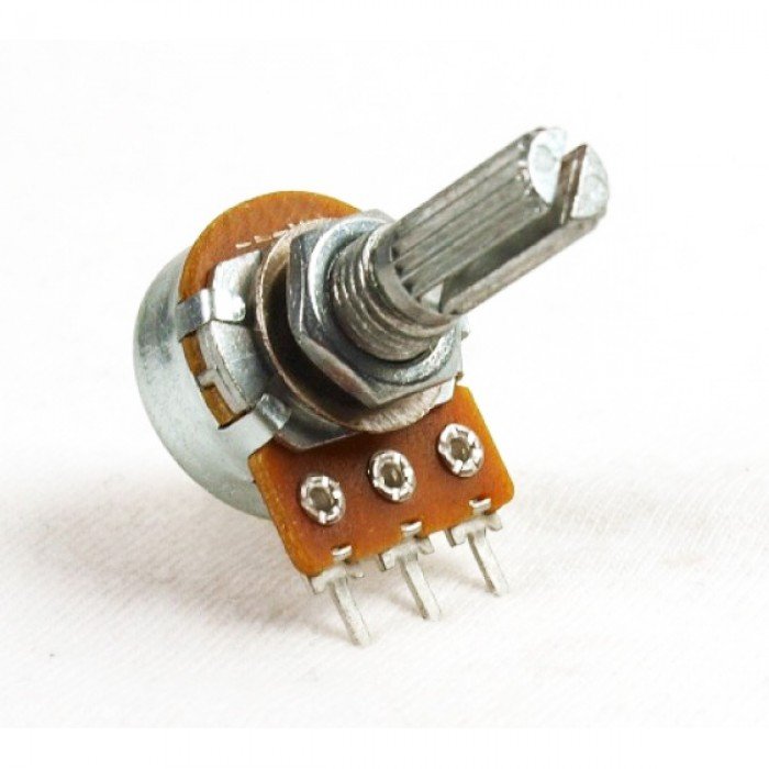
Analog Input: 10K Ohm linear taper potentiometer for smooth voltage variation.
Prototyping: 400-point solderless breadboard for secure component mounting.
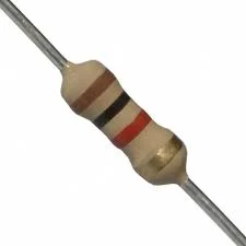
Current Limiting: 220 Ohm resistor to protect the visual indicator.
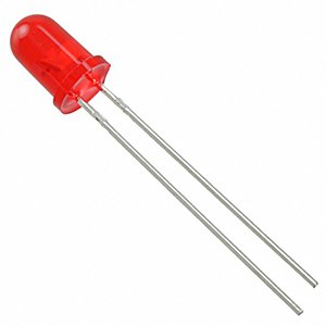
Output: 5mm diffused LED for real-time brightness or blink rate feedback.
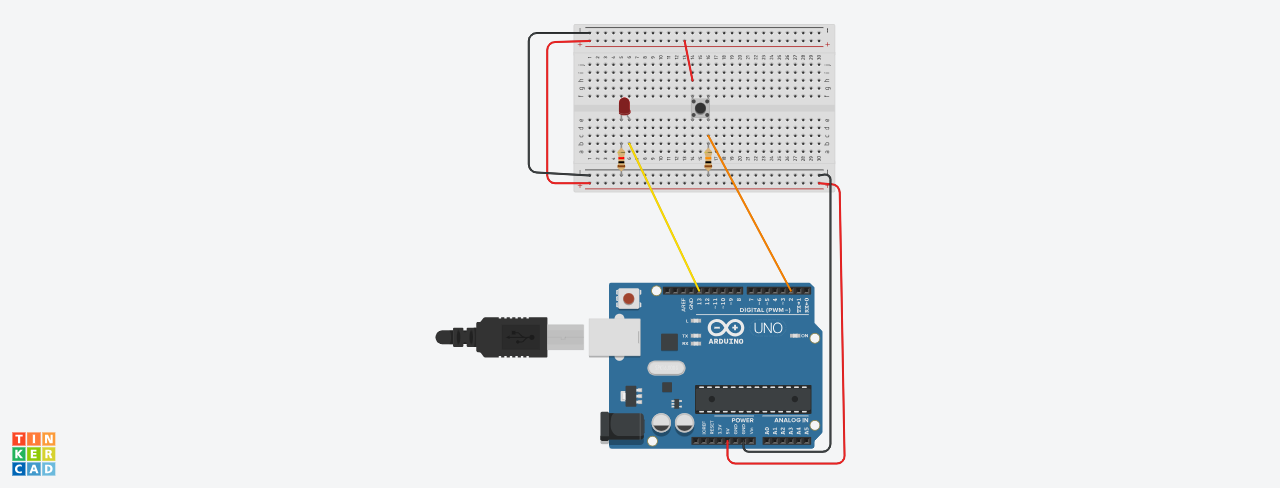
Circuit Wiring and Usage
First, connect the potentiometer outer pins to 5V and GND rails.
Link the center wiper pin to the Arduino analog input A0.
Then, wire the LED in series with the resistor to a PWM-capable digital pin.
Afterward, rotate the dial to change values in the Serial Monitor.
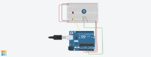
This diagram shows all kit components connected to simulate working.
Advantages and Disadvantages of the Arduino Potentiometer Sensor Kit
Pros: Provides a tactile way to interact with software variables in real-time.
Furthermore, it offers a fundamental understanding of how sensors provide data to microcontrollers.
Cons: Mechanical potentiometers can wear out over thousands of rotations.
Precautions and Safe Handling
Never connect the 5V and GND directly through the wiper pin without resistance.
Ensure the potentiometer is seated firmly in the breadboard to avoid fluctuating readings.
What is Included in the Package
1x Arduino UNO Compatible Board
1x 10K Ohm Potentiometer
1x 400-Point Breadboard
1x 220 Ohm Resistor
1x 5mm LED
AND PLEASE NOTE THAT ALL COMPONENTS ARE UN-ASSEMBELED. You have to assemble the kit your self.
DRIVE LINK FOR .ino FILE AND CIRCUIT DIAGRAM: Click Here
Tutorial on how to use this: Click Here
Order more Learning Kits from AmpFlick: Click Here
🔗 Connect with the Ampflick Community
Stay updated with the latest hardware arrivals, project ideas, and engineering mentorship in Pakistan!
Instagram: @Ampflick — Daily project reels & hardware fashion.
LinkedIn: Ampflick Tech — Professional networking & career opportunities.
WhatsApp Support: Link to WhatsApp — Technical queries and bulk orders.
YouTube: Ampflick Official — Hardware masterclasses.
Only logged in customers who have purchased this product may leave a review.
Related products

-
Sale!
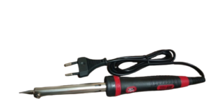
Soldering iron (220V) 60W
- Original price was: ₨680.00.₨650.00Current price is: ₨650.00.
- Add to cart
-
Sale!

-
Sale!
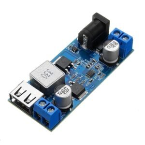
DC-DC 24V/12V To 5V 5A Step Down Power Supply Buck Converter Module | AmpFlick
- Original price was: ₨450.00.₨430.00Current price is: ₨430.00.
- Add to cart
-
Sale!

Reviews
There are no reviews yet.