A Line Follower Robot (LFR) is one of the most widely built Arduino-based robotics projects and is a great way to learn the fundamentals of automation and sensor integration. This step-by-step tutorial will guide you through building a high-quality line follower robot using an Arduino UNO, complete with detailed code explanations. Ideal for both beginners and intermediate enthusiasts. This project teaches essential skills such as hardware connections, sensor tuning, and motor control. Once you’ve built the basic version, you can take it further by upgrading it into a maze-solving robot that not only follows a path but also intelligently navigates a maze to find the exit on its own.
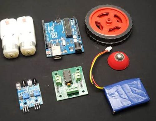
Components Required to build line following Robot
- Arduino UNO
- IR Sensors
- L298N Motor Driver
- DC Motor
- Wheels
- Chassis
- Battery Pack
- Jumper Wires
You’ll also need some basic tools such as a soldering iron and solder, wire stripper, screwdrivers, and a hot glue gun for assembly and wiring. It’s also a good idea to keep a few extra items on hand, like a battery level indicator, a power switch for easy control, and a spare IR sensor module for future upgrades.
Description
In this project, we build a simple line-following robot using an Arduino UNO. The robot follows a black line on a white surface by using IR sensors. These sensors sit at the front of the robot and help it detect the position of the line. When the sensors find the black line, they send signals to the Arduino. The Arduino reads the input and decides whether the robot should move straight, turn left, or turn right to stay on the line. Two DC motors, connected to wheels, drive the robot forward. An L298N motor driver controls these motors and receives commands from the Arduino. We attach all the components to a basic chassis (robot frame) and power the system with a battery pack. This project helps you learn the basics of robotics, automation, and how to use sensors with microcontrollers.

WORKING Principal of line following robot
The line-following robot works by using infrared (IR) sensors to detect the line on the ground. These sensors shine infrared light onto the surface and measure how much light is reflected back. A white surface reflects more light, while a black line absorbs most of the light. The robot has two or more IR sensors placed in the front.If the left sensor goes over the black line, the Arduino understands that the robot needs to turn left. If the right sensor detects the black line, the robot turns right. This way, the Arduino is constantly checking the sensor values and giving instructions to the L298N motor driver, which controls the DC motors to move the robot in the correct direction. By doing this continuously, it follows the line smoothly and automatically.
Circuit Diagram of Line Following Robot
Understanding the Circuit
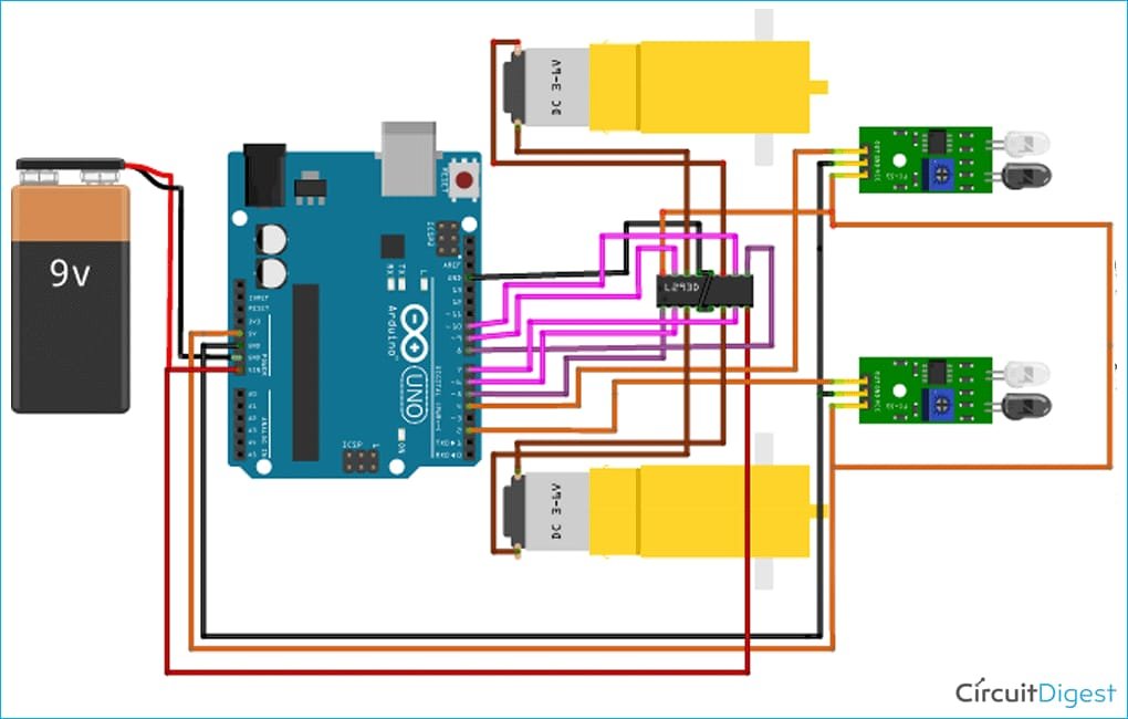
This image shows the complete circuit layout for a simple line-following robot built with an Arduino UNO. It can follow a black line on a white surface (or vice versa) by using sensors that detect light and dark areas on the ground.
Let’s break down the key components and how they all connect:
Arduino UNO
This is the brain of the robot. It reads signals from the sensors and tells the motors when and how to move so the robot stays on the line.
9V Battery
The battery powers the entire circuit, including the Arduino and the motors.
L293D Motor Driver
This chip acts like a middleman between the Arduino and the motors. It takes low-power signals from the Arduino and uses them to control the direction and speed of the motors.
DC Motors (3–6V)
These motors spin the wheels to move the robot. The motor driver controls their speed and direction depending on what the Arduino tells it to do.
Line Sensors (IR Sensors)
These sensors help the robot to see the line on the ground. Each sensor has an infrared LED that shines light down, and a phototransistor that detects how much light bounces back. When the sensor passes over a dark line, less light reflects, and it sends a LOW signal. Over a white surface, more light reflects, and the sensor sends a HIGH signal.
How the Circuit Connects:
- The 9V battery connects to the Vin and GND pins on the Arduino to power it.
- The L293D motor driver connects to Arduino digital pins to receive movement commands. It also connects to the 9V battery for power and to the motors to control them.
- The motors connect to the output pins on the motor driver so they spin as directed.
- The line sensors connect to the analog pins on the Arduino so it can read line positions in real-time. They also connect to 5V and GND for power.
How it Follows a Line:
As the robot moves, it continuously checks the readings from the sensors:
- If both sensors see the line, the robot moves straight.
- If only one sensor sees the line, the robot turns slightly to adjust.
- The Arduino keeps making these small corrections so the robot stays on track.
Programming, Testing, Troubleshooting & Upgrading Your Line Following Robot
Arduino Code for Line Following Robot
In this part, you’ll write the actual program (called a “sketch”) that tells the robot how to behave. The Arduino reads values from the IR sensors and uses simple if-else conditions to decide whether the robot should move straight, turn left, or turn right. This code also sends signals to the motor driver to control the motors. Each movement depends on what the sensors detect — for example, if both sensors see white, the robot moves forward; if one sensor sees black, it turns to correct its path.
Uploading the Code and Testing the Robot
After writing the code, you connect your Arduino UNO to your laptop using a USB cable and upload the program through the Arduino IDE. Once the code is uploaded successfully, disconnect the USB, power the robot using a battery pack, and place it on a black line over a white surface. Watch how the robot follows the line! You may need to adjust sensor positions or tweak the code slightly to improve performance.
Common Issues and Troubleshooting
If your robot doesn’t work correctly, don’t worry small issues are common and easy to fix. For example:
- If the motors aren’t spinning, check the power and motor driver connections.
- If the robot doesn’t follow the line, check if the IR sensors are working properly and are close enough to the ground.
- If the robot turns the wrong way, make sure the sensors are connected to the correct pins in the code.
Testing and making changes is part of the learning process.
Improvements and Future Upgrades
Once your basic robot is working, you can make it even cooler! Try using 3 or more sensors to improve accuracy, or implement PID control for smoother movements. You can also upgrade the battery for longer use or even turn your robot into a maze-solving bot. Other fun add-ons include Bluetooth modules to control the robot with your phone, or LEDs to show direction indicators.
If you want to order top quality component for your IOT project than visit our website Ampflick
You can also visit our Instagram and Facebook for latest update.

