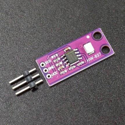
GUVA-S12SD UV Light Sensor Module price in pakistan
Original price was: ₨1,575.00.₨1,496.00Current price is: ₨1,496.00.
Delivered All over Pakistan 🇵🇰
Description
The first stage op amp outputs a voltage proportional to 4.3 * sensor photocurrent in µA. If the photocurrent is 0.1µA (0.09mW/cm^2), then the output will be 0.43V
This feeds a second stage op amp with an additional gain of 6.1x. In this example the final output will be 0.43V x 6.1 = 2.62V.
As configured, the module is mainly useful for measuring moderate to moderately high UV light levels or if the sensor is placed behind a neutral density filter to reduce the percentage of UV striking the sensor.
If it is desired to measure very high UV levels, the second stage of amplification can be bypassed. This can be accomplished by shorting across the 5.1K resistor “512”and removing the 1K resistor to the right of it with marking “01B” or “102”. This changes the gain of the output op amp to x1 effectively taking it out of circuit. With that modification, UV index is then calculated by multiplying the output by 10.
Please note: As of 6/2021, we are modifying this module and it now ships with a 1M feedback resistor on the first stage as noted above. Prior to that date, the feedback resistor was 10M. 10M resistors are marked 01F, 1M resistors are marked 01E. With a 10M feedback resistor, the first stage is 43 * sensor photocurrent in µA. If the photocurrent is 0.1µA (0.09mW/cm^2), then the output will be 4.3V.
Module Connections
The module brings out the following connections.
1 x 3 Header
SIG or SIO = Signal Output – Connect to MCU analog input
GND = Ground
VCC = 2.7V to 5.5V. Connect to Vcc of the MCU (typically 3.3 or 5V)
Module Assembly
The module ships with the male header strip loose. The header can be soldered to the top or bottom of the module depending on the planned use or wires can be used to make the connections.
For breadboard use, we put the headers on the bottom. Soldering is easiest if the header is inserted into a solderless breadboard to hold it in position during the soldering process.
OUR EVALUATION RESULTS:
GUVA-S12SD UV Sensor Module – Testing
The program below simply reads the output of the sensor every second and prints the raw reading and UV Index to the Serial Monitor window.
To use this program you will want a source of UV which can be the sun or something like a black light as shown in the picture to the right. The nice thing about a black light is that by changing the distance to the sensor, you can see that the output of the sensor changes to match the intensity of the UV falling upon the sensor.
The sensor is connected to analog pin A0, but this can be changed to any convenient analog input. Also be sure to provide power and ground. We are using 5V in this example.
Only logged in customers who have purchased this product may leave a review.
Related products
-
-
Sale!
24C256 interface EEPROM Memory Module Price in Pakistan
- Original price was: ₨788.00.₨749.00Current price is: ₨749.00.
- Add to cart
-
Sale!
-
-
Sale!
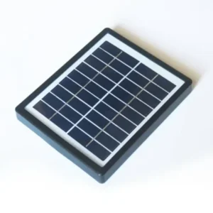
12V 2W mini Solar Panel Price in Pakistan
- Original price was: ₨840.00.₨798.00Current price is: ₨798.00.
- Add to cart
-
Sale!
Reviews
There are no reviews yet.