
Autonomous AI Soccer Robot – 4 Wheel Edition
Original price was: ₨12,000.00.₨10,000.00Current price is: ₨10,000.00.
Delivered All over Pakistan 🇵🇰
A high-performance autonomous soccer robot featuring a six-wheel drive system, intelligent camera vision, obstacle detection, and a smart ball-handling mechanism. Designed for robotic soccer competitions, research, and STEM education.
Description
Autonomous AI Soccer Robot – Six-Wheel Edition
Complete Product Description, Electrical Circuit & Component Documentation
1. Product Overview
The Autonomous AI Soccer Robot is a six-wheel robotic platform designed for intelligent soccer gameplay, autonomous navigation, ball detection, obstacle avoidance and ball shooting.
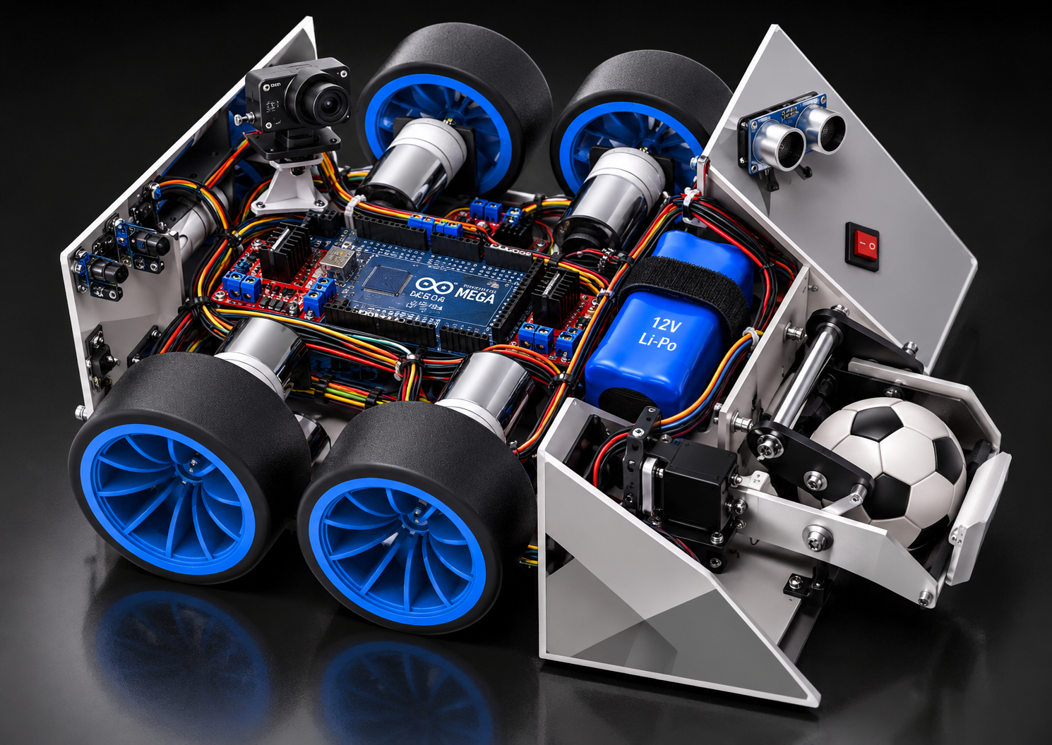
The robot is developed around the original six-wheel chassis, featuring six DC geared motors, black tires with blue rims, individual motor mounting brackets, a central electronics compartment and angled protective side panels.
The system combines embedded electronics, computer vision, motor control, sensors and a ball-handling mechanism to create an autonomous robotic soccer player.
Main objectives:
- Autonomous movement and navigation.
- Football detection and tracking.
- Ball collection and positioning.
- Obstacle detection and avoidance.
- Intelligent movement towards the opponent’s goal.
- Controlled ball shooting.
- Remote-control operation for testing and manual driving.
2. Mechanical System
The original chassis design will remain the foundation of the robot.
| Component | Quantity | Function |
|---|---|---|
| Main chassis | 1 | Structural frame |
| DC geared motors, 12V 350RPM | 6 | Wheel propulsion |
| 65mm wheels | 6 | Robot movement |
| Motor mounting brackets | 6 | Motor installation |
| Motor-to-wheel couplers | 6 | Mechanical connection |
| Side protective panels | 2 | Mechanical protection |
| Front ball guide | 1 | Guides ball into the handling area |
| Ball intake roller | 1 | Ball collection |
| Kicker mechanism | 1 | Ball shooting |
The ball intake and kicker are additional proposed mechanisms, not confirmed components of the original CAD assembly.
3. Electronic Components List
A. Main Control System
| Component | Quantity | Purpose |
|---|---|---|
| Arduino Mega 2560 | 1 | Main motor and sensor controller |
| Raspberry Pi 5 | 1 | Computer vision and AI processing |
| Raspberry Pi camera module or USB camera | 1 | Ball and goal detection |
| MicroSD card | 1 | Raspberry Pi operating system and software |
B. Motor Control System
| Component | Quantity | Purpose |
|---|---|---|
| 12V 350RPM DC geared motors | 6 | Wheel drive |
| Dual-channel motor drivers | 3 | Independent control of six motors |
| Motor driver heat sinks | As required | Thermal management |
| Motor wiring | As required | Power and control connections |
| Motor encoders | Up to 6 | Wheel speed and position feedback |
Important: Select motor drivers based on the actual motor stall current, not just the nominal 12V rating. Each driver channel must safely handle its motor’s startup and stall current.
A suitable driver family to investigate is Cytron MDD10A, provided the measured motor current is within its ratings.
C. Sensors and Vision
| Component | Quantity | Purpose |
|---|---|---|
| Camera module | 1 | Football and goal recognition |
| HC-SR04 ultrasonic sensors | 3 | Obstacle distance measurement |
| IR obstacle sensors | 2 | Close-range obstacle detection |
| Wheel encoders | 6 | Movement feedback |
| IMU sensor (MPU6050) | 1 | Orientation and movement measurement |
D. Power Supply
| Component | Quantity | Purpose |
|---|---|---|
| 3S LiPo battery, 11.1V nominal | 1 | Main power source |
| Battery protection / low-voltage monitoring | 1 | Battery protection |
| Balance charger | 1 | Battery charging |
| DC-DC buck converter, 5V | 1 | Logic power |
| Separate 5–6V regulator | 1 | Servo power |
| Main fuse and holder | 1 | Electrical protection |
| Emergency stop switch | 1 | Motor power shutdown |
| Power distribution block | 1 | Power distribution |
| Battery connector | 1 | Battery connection |
Battery capacity and discharge rating must be selected after measuring the combined motor current and estimating operating time.
E. Ball Handling System
| Component | Quantity | Purpose |
|---|---|---|
| Ball intake roller | 1 | Captures football |
| Geared DC motor | 1 | Drives intake roller |
| Motor driver | 1 | Controls intake motor |
| High-torque servo | 1 | Controls mechanical kicker |
| Kicker plate | 1 | Pushes the ball |
| Ball guide rollers | As required | Maintains ball positioning |
4. Complete Electrical Circuit Diagram
The following is the proposed electrical architecture. It shows the connections between the battery, controllers, motor drivers, sensors and motors.
                 3S LI-PO BATTERY
                    11.1V
                       |
                 MAIN FUSE
                       |
                EMERGENCY STOP
                       |
                POWER DISTRIBUTION
                       |
          +------------+-------------+
          |            |             |
          |            |             |
      MOTOR POWER   5V BUCK       5-6V REGULATOR
          |            |             |
     +----+----+       |             |
     |    |    |       |             |
    MD1  MD2  MD3   ARDUINO       SERVO
     |    |    |    MEGA 2560     KICKER
     |    |    |
    M1-M2 M3-M4 M5-M6
    SIX DC MOTORS

                  ARDUINO MEGA
                       |
          +------------+-------------+
          |            |             |
       Sensors     Motor Drivers   Encoders
          |
    Ultrasonic / IR

              RASPBERRY PI 5
                    |
                  CAMERA
                    |
             COMPUTER VISION
                    |
             SERIAL COMMUNICATION
                    |
               ARDUINO MEGA
Electrical connection principles:
- Battery positive connects through the main fuse and emergency stop to the motor power distribution.
- The motor drivers receive battery voltage within their rated operating range.
- Each driver controls two independent motor channels.
- Arduino Mega provides PWM and direction signals to the three dual-channel motor drivers.
- The Arduino receives sensor and encoder signals.
- Raspberry Pi processes camera images and sends navigation commands to the Arduino over serial communication.
- A regulated 5V supply powers the Arduino and compatible sensors.
- A separate suitably rated 5–6V regulator powers the servo.
- All control electronics and motor drivers share a common signal ground.
- The motor supply and logic supply must be properly protected and regulated.
Safety: Do not connect motors directly to Arduino pins. Do not power the servo directly from the Arduino 5V pin. The battery fuse, emergency stop, wire gauge and driver ratings must be selected for the actual current.
5. Arduino Mega Pin Connection Plan
The following is an example pin assignment for three dual-channel motor drivers.
| Driver | Motor | PWM Pin | Direction Pins |
|---|---|---|---|
| Driver 1 | Left front | 2 | 22, 23 |
| Driver 1 | Left middle | 3 | 24, 25 |
| Driver 2 | Left rear | 4 | 26, 27 |
| Driver 2 | Right front | 5 | 28, 29 |
| Driver 3 | Right middle | 6 | 30, 31 |
| Driver 3 | Right rear | 7 | 32, 33 |
Additional connections:
| Device | Arduino connection |
|---|---|
| Front ultrasonic trigger | D34 |
| Front ultrasonic echo | D35 |
| Left ultrasonic trigger | D36 |
| Left ultrasonic echo | D37 |
| Right ultrasonic trigger | D38 |
| Right ultrasonic echo | D39 |
| IR sensors | D40, D41 |
| Intake motor driver | D8 and D42 |
| Kicker servo signal | D9 |
| Raspberry Pi serial TX/RX | Serial1, D18/D19 |
| IMU sensor | I2C SDA/SCL, D20/D21 |
This is a proposed pin map, not a verified wiring harness. Encoder inputs, voltage levels, driver interfaces and available pins must be checked before construction.
6. Software and Artificial Intelligence
The robot uses two processing levels.
Arduino Mega firmware
- Six-motor speed control.
- Forward and reverse movement.
- Left and right turning.
- Motor speed balancing.
- Sensor readings.
- Encoder feedback.
- Emergency-stop handling.
- Intake and kicker control.
Raspberry Pi software
- Camera image processing.
- Football recognition.
- Goal detection.
- Object tracking.
- Obstacle recognition.
- Navigation decisions.
- Communication with Arduino.
Recommended software:
- Python
- OpenCV
- Arduino IDE
- C/C++
- Raspberry Pi OS
7. Autonomous Robot Operating Sequence
- Robot starts and checks its battery and sensors.
- Camera begins scanning the playing field.
- AI identifies the football.
- Navigation software calculates the ball’s position.
- Robot moves towards the football.
- The ball intake mechanism collects and positions the football.
- Camera identifies the opponent’s goal.
- Robot aligns itself towards the target.
- Kicker mechanism shoots the football.
- Robot searches for the next opportunity.
8. Power and Performance Considerations
- The six wheel motors require a high-current power distribution system.
- The 3S battery provides 11.1V nominal and 12.6V when fully charged.
- Confirm that the motor is rated for the complete battery voltage range.
- Use separate regulated supplies for logic and high-current servos.
- Use motor encoders for improved straight-line movement.
- Test the robot with its wheels lifted before floor operation.
- Monitor motor-driver temperature and battery voltage.
Actual speed, torque, operating time and shooting performance will depend on the selected battery, motor specifications, wheel traction and final robot weight.
9. Assembly and Development Plan
| Phase | Development task |
|---|---|
| 1 | Preserve and assemble original six-wheel chassis |
| 2 | Install six motors and wheel couplers |
| 3 | Install motor drivers and power distribution |
| 4 | Install Arduino Mega and Raspberry Pi |
| 5 | Install camera and distance sensors |
| 6 | Install battery and safety system |
| 7 | Develop and test motor-control firmware |
| 8 | Develop camera-based ball detection |
| 9 | Install ball intake and kicker |
| 10 | Perform autonomous soccer testing |
10. Final Product Specifications
| Specification | Proposed configuration |
|---|---|
| Robot type | Autonomous soccer robot |
| Drive system | Six-wheel drive |
| Drive motors | 6 × 12V 350RPM DC motors |
| Wheel diameter | 65mm |
| Main controller | Arduino Mega 2560 |
| AI computer | Raspberry Pi 5 |
| Vision system | Camera-based computer vision |
| Obstacle detection | Ultrasonic and IR sensors |
| Battery | 3S 11.1V LiPo |
| Motor control | 3 dual-channel motor drivers |
| Ball handling | Powered roller and mechanical kicker |
| Programming | Arduino C/C++ and Python |
| Operating modes | Autonomous and manual testing |
11. Conclusion
The Autonomous AI Soccer Robot combines a six-wheel mechanical platform with embedded control electronics, camera-based artificial intelligence, distance sensing and an active ball-handling mechanism.
The proposed system is designed to transform the existing chassis into a complete robotic soccer platform capable of detecting a football, navigating the playing area, avoiding obstacles, controlling the ball and shooting towards the goal.
Design commitment: The original six-wheel chassis, wheel arrangement, motor positions and protective side panels are retained as the mechanical foundation. New electronic and ball-handling components are added around that design.
Documentation status: Proposed engineering design. Final wiring, component ratings, mechanical clearances and firmware must be verified before fabrication and powered testing.
Only logged in customers who have purchased this product may leave a review.
Related products


Blutooth Unit HC-05
- ₨810.00
- Add to cart

V3 VOICE Unit
- ₨4,750.00
- Add to cart


Reviews
There are no reviews yet.