
Smart Density-Based Traffic Control System
₨2,220.00
Delivered All over Pakistan 🇵🇰
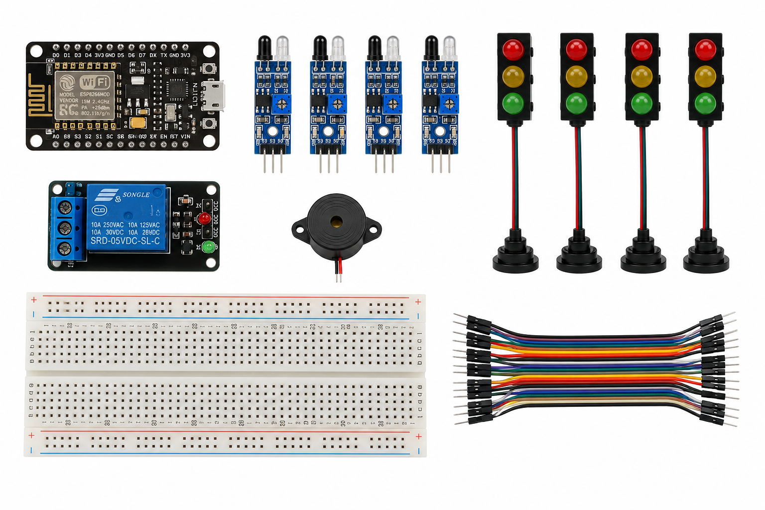
The Density-Based Traffic Control System is an unassembled IoT project using NodeMCU, IR sensors, and LED traffic lights to detect vehicle density and manage signals automatically. It is ideal for smart city, IoT, and final-year projects.
Description
Introduction to Density-Based Traffic Control System
The Density-Based Traffic Control System is a smart IoT project designed for automated traffic management. It adjusts traffic signals according to the number of vehicles on each road. The system uses NodeMCU, IR sensors, and LED traffic lights to monitor traffic conditions.Moreover, the project demonstrates how IoT technology can improve traffic signal management. In addition, it helps users understand embedded systems, automation, and smart transportation. Furthermore, its practical design makes it suitable for students, hobbyists, and engineering projects. Therefore, it provides an effective platform for learning modern traffic control concepts.
How Density-Based Traffic Control Works
The system uses four IR obstacle sensor modules to detect vehicles on different roads. First, the sensors identify vehicles approaching the intersection. Next, the NodeMCU ESP8266 receives the sensor signals.Then, the controller compares the traffic levels on each road. After that, it adjusts the traffic-light sequence according to the detected vehicle density. As a result, roads with heavier traffic can receive more suitable signal time.Furthermore, the NodeMCU provides built-in Wi-Fi connectivity. Consequently, the system can support IoT-based monitoring and future connectivity features. Meanwhile, the piezo buzzer can provide an audible indication during selected operations. Thus, the project demonstrates how sensor data can control traffic signals automatically.
Key Features & Specifications
- Controller: NodeMCU ESP8266
- Detection: 4-channel vehicle monitoring
- Sensors: IR obstacle sensor modules
- Traffic Lights: Red, yellow, and green LEDs
- Control: Automatic signal management
- Technology: IoT and embedded systems
- Connectivity: Built-in Wi-Fi
- Monitoring: Real-time traffic detection
- Alert: Piezo buzzer
- Project Type: Smart city and IoT project
- Learning Areas: Traffic control, automation, and programming
- Use: Educational projects, prototypes, and demonstrations
Applications & Use Cases
The Density-Based Traffic Control System is suitable for smart city projects and final-year projects. For example, students can demonstrate how traffic signals respond to changing vehicle density.In addition, the system supports IoT education, traffic management experiments, and embedded-system projects. Similarly, users can study how sensors collect information and how controllers use that data for automated decisions.Furthermore, the NodeMCU allows users to expand the system with additional features. For instance, they can integrate cloud platforms, mobile applications, displays, or additional sensors. As a result, the project can support more advanced IoT and smart transportation experiments.Overall, this system provides hands-on experience with vehicle detection, NodeMCU programming, IoT communication, traffic signals, and automated traffic control. Therefore, it offers a practical platform for exploring intelligent transportation and IoT-based automation.
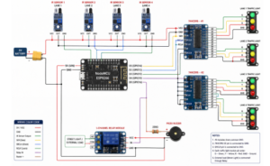
Function: Four IR sensors estimate traffic density. The system uses the highest detected density to determine the green-light duration. A buzzer indicates a traffic-cycle change and a relay provides an optional control output.
Connections
| Component | NodeMCU Pin |
| IR Sensor 1 OUT | D1 |
| IR Sensor 2 OUT | D2 |
| IR Sensor 3 OUT | D5 |
| IR Sensor 4 OUT | D6 |
| Red LED | D7 |
| Yellow LED | D0 |
| Green LED | D3 |
| Buzzer + | D4 |
| Relay IN (optional) | RX / GPIO3 |
| VCC | 5V/VU |
| GND | GND |
Hardware note: Four independent RGB traffic-light sets require more GPIO than is conveniently available on the NodeMCU. For four independently controlled intersections, add a GPIO expander such as 74HC595, PCF8574, or MCP23017.
#define IR1 D1
#define IR2 D2
#define IR3 D5
#define IR4 D6
#define RED_LED D7
#define YELLOW_LED D0
#define GREEN_LED D3
#define BUZZER D4
#define RELAY 3
void setup() {
Serial.begin(115200);
pinMode(IR1, INPUT); pinMode(IR2, INPUT);
pinMode(IR3, INPUT); pinMode(IR4, INPUT);
pinMode(RED_LED, OUTPUT); pinMode(YELLOW_LED, OUTPUT);
pinMode(GREEN_LED, OUTPUT); pinMode(BUZZER, OUTPUT);
pinMode(RELAY, OUTPUT);
digitalWrite(RELAY, LOW);
allLightsOff();
}
void loop() {
int d1 = readDensity(IR1);
int d2 = readDensity(IR2);
int d3 = readDensity(IR3);
int d4 = readDensity(IR4);
int maxDensity = max(max(d1, d2), max(d3, d4));
int greenTime = maxDensity >= 3 ? 15000 :
maxDensity >= 2 ? 10000 :
maxDensity >= 1 ? 7000 : 5000;
digitalWrite(GREEN_LED, HIGH);
digitalWrite(RED_LED, LOW);
digitalWrite(YELLOW_LED, LOW);
digitalWrite(RELAY, HIGH);
delay(greenTime);
digitalWrite(GREEN_LED, LOW);
digitalWrite(YELLOW_LED, HIGH);
digitalWrite(RELAY, LOW);
tone(BUZZER, 1000);
delay(1000);
noTone(BUZZER);
digitalWrite(YELLOW_LED, LOW);
digitalWrite(RED_LED, HIGH);
delay(5000);
}
int readDensity(int sensorPin) {
int count = 0;
for (int i = 0; i < 5; i++) {
if (digitalRead(sensorPin) == LOW) count++;
delay(50);
}
return count;
}
void allLightsOff() {
digitalWrite(RED_LED, LOW);
digitalWrite(YELLOW_LED, LOW);
digitalWrite(GREEN_LED, LOW);
}
Only logged in customers who have purchased this product may leave a review.
Related products

RC Car Tyre/wheel
- ₨120.00
- Add to cart
Reviews
There are no reviews yet.